I love vu meters. I mean it I really really like them. So with me doing so much work on psp's over the years I knew that I would one day end up trying to fit one in a psp some how. I should say before I start that this is only a semi finished project. My psp (the one I use for gaming) has a full vu meter installed, however I have plans to do an entirely new revision of this, which I will go into more detail about later.
For those of you not in the know a VU meter displays signal level in Visual Units. They are often seen in audio equipment an are usually ether a needle or led display. Heres one here look . . .

There are two ways that I know of of building a vu circuit. One is with a ic that is designed for it called a LM3915. This is relatively simple to use and would be perfect for what I want to achieve. I didnt have one of those though. The other way is using several opamps. I had some of those. So the design I went for in this first revision was 2 quad opamps called LM324's Heres an schematic of that circuit. Please note that this is not the actual one I used as I had to modify that for use with the psp. I do have that schematic but its currently residing in my desk tops HD in storage. I'll update this when I get set up back in the UK.

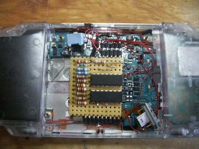
So after a little research and some trial and error on a bread board I built a circuit on a bit of proto board that fited nicely into the somewhat redundant umd drive space of my psp. Heres an image of how that looks.
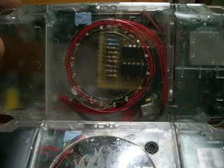
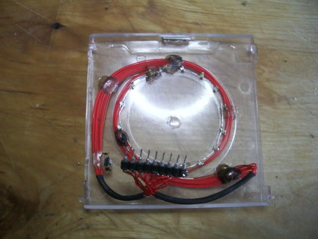
I then added 16 smt leds to the umd door. This was hooked up to the circuit using pin headers as a makeshift plug. I also used this method for hooking up the power ground and audio lines from the psp. Heres an image of the door led set up.
This dose work very nicely but I would prefer to do this in a more elegant way. For the next revision of this mod I intend to go fully smt using a smt LM3915 and an etched circuit board. Using this method I should easily be able to fit the pcb into another area of the psp should I want to use the umd drive. I may also add a picaxe to handle changing modes and colours.Stay posted for an update once that has been finished. I will then be offering that mod through my pro modding service :)
Ive had a request for a video of my psp in action so here it is. . . .


Nice job man! Keep the modding world alive!
ReplyDeletebadasss, great song too!
ReplyDeleteGob job man!
ReplyDeleteAs far as i know you made an ADC from the discrete part... why didn't you use a pre-made ADC?
Do I see an Offspring logo there?
ReplyDeleteHa. Well spotted. That was on an early version of this mod. They guy I made it for had a custom engraved door with the flaming skull logo on it.
ReplyDeleteThat's pretty awesome, however, does it effect the battery life?
ReplyDeleteLovvely blog you have
ReplyDelete